Solid Late
Reindeer LED FabLab Project
Summary report
06 May 2018 » post by: aleks greta julia lorinc
Reindeer LED FabLab Project
06 May 2018 » post by: aleks greta julia lorinc
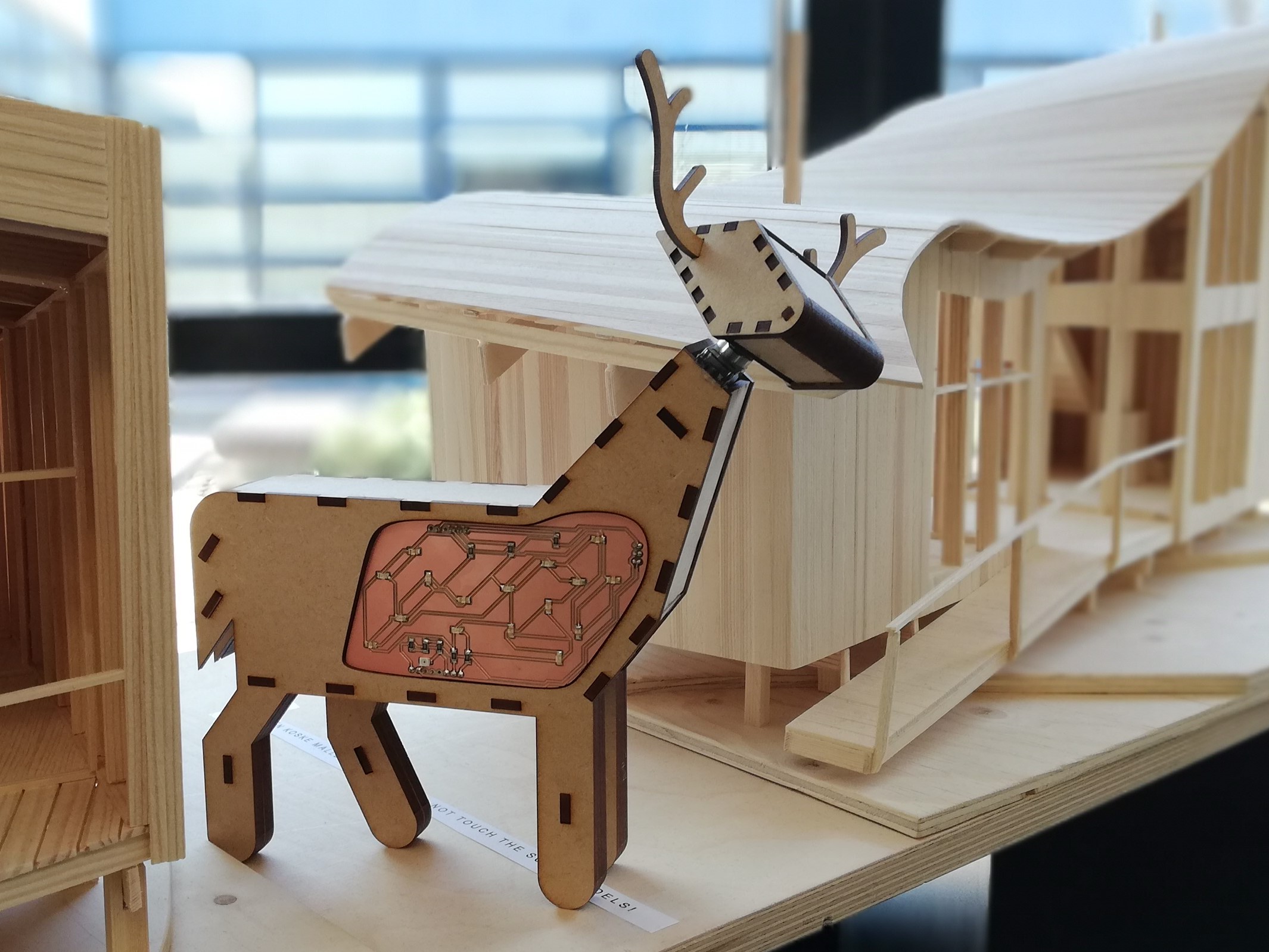
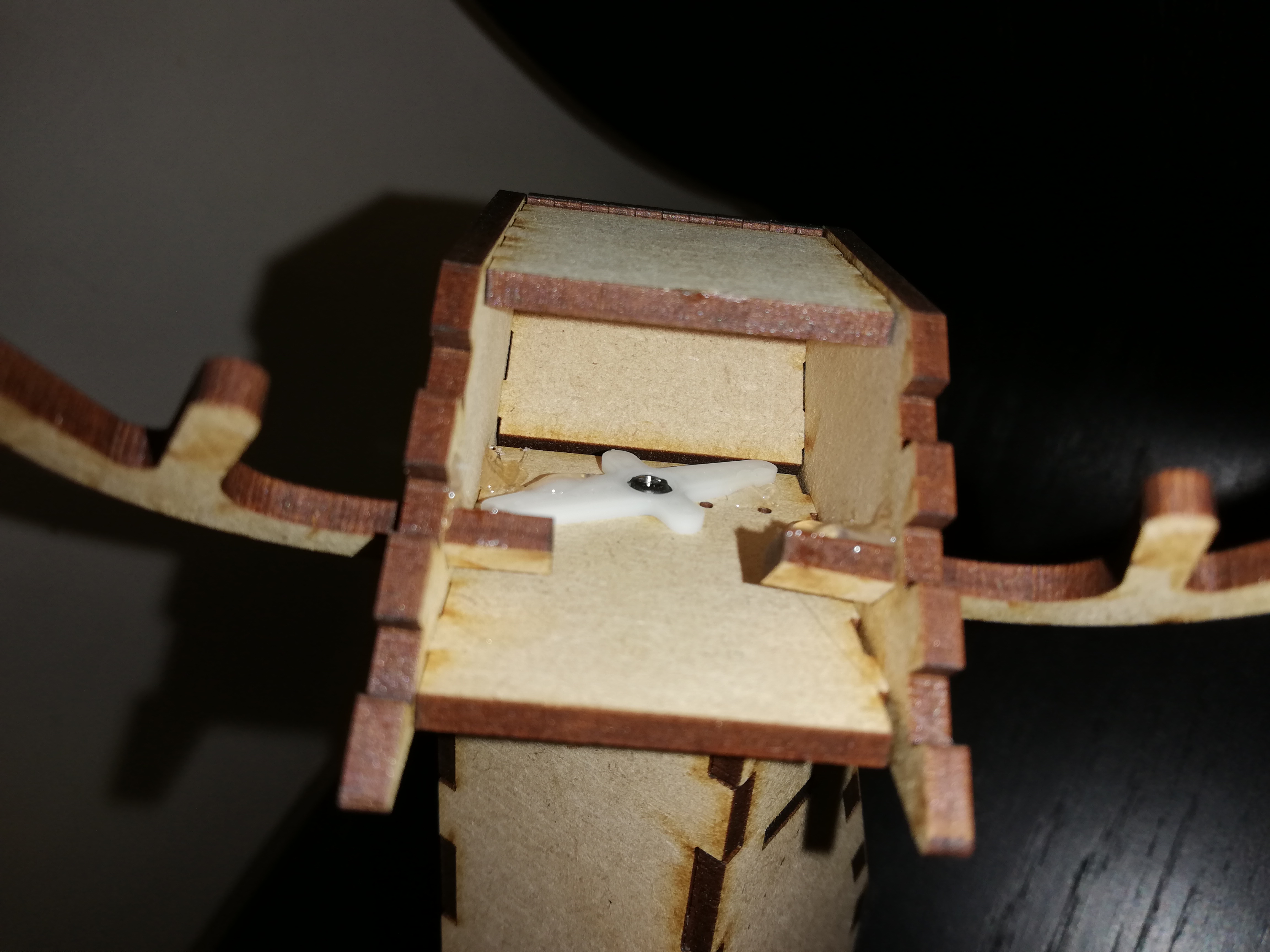
Our end result is a reindeer made of wood which glows orange-blue. The LEDs can blink in different patterns and are depending on the light in the surroundings. The head is movable which gives the animal a curious look.
Our final model consists of the following parts:
The first ideas were based on ambient light and could be understood as a piece of furniture or decoration. From the very beginning, we have preferred wood for its naturalness. After collecting some of the ideas we decided to stick to the reindeer form, which reminded us of our stay in Finland. The sketches and detailed progress of our idea finding progress can be looked up in the drafts category.
In the second step we divided up the work and tried to work as parallel as possible. One team worked on the reindeer shape and moving head, the second one created the circuit board and programmed the LEDs. The instructions provided in the internet by FabLab and the friendly support of the staff helped us a lot in using the laser cutter and milling machine to reach our goal. Both teams exchanged their progress often because we stumbled over some problems on both sides and the reindeer and circuit board design were subject of some changes.
Our aim was to give our product a reindeer shaped geometry. As we agreed on using wood as the material of the product the manufacturing method was laser cutting of FMD sheets of 3 mm thickness. This method set some limitations on the geometry as it is only able to cut 2D drawings out of sheets, so the final 3D model was realized by the extrusion of a 2D sketch. For modelling we used Fusion 360.
First we manufactured the shape of the front panel to check if it fits all the electronic components. We decided that the geometry should be slightly bigger, so we would reach the electronic components easily and it will be easier to assemble the product.
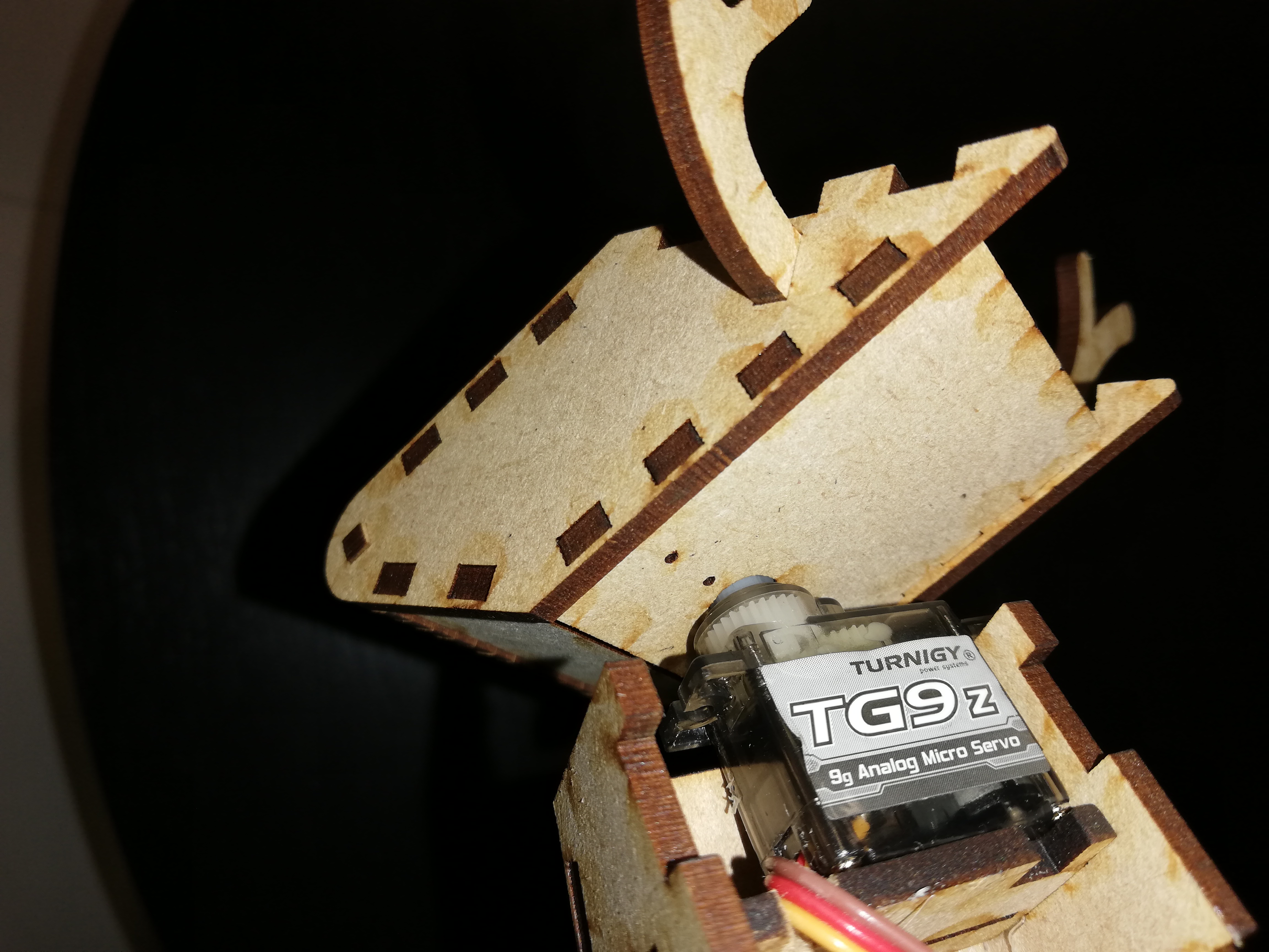
The second prototype was an assembly of wooden sheets and it was fixed by some overlapping parts. We noticed that on of the components does not fit because the size of it was uncorrect. In this model the place of the servo motor was in the bottom part of the neck and we agreed on changing it and putting it in the top part of the neck, so this way no rods should be attached to the gear to forward the torque to the rotating head.
In the third prototype all the changes were implemented so we attached servo motor to the top part of the neck. After the assembly was done we wanted to insert the customized shaped PCB and we realized that we did the assembly with the wrong direction, so the PCB did not fit the cut on the front panel.
For the fourth prototype we reproduced the same parts as for the third prototype and we did the assembly with the right direction. We reused the head from the third prototype so we haven’t had to laser cut it again. This prototype fit all the requirements so it is the final version of the prototype.
The sketches which were used for the laser cutting:
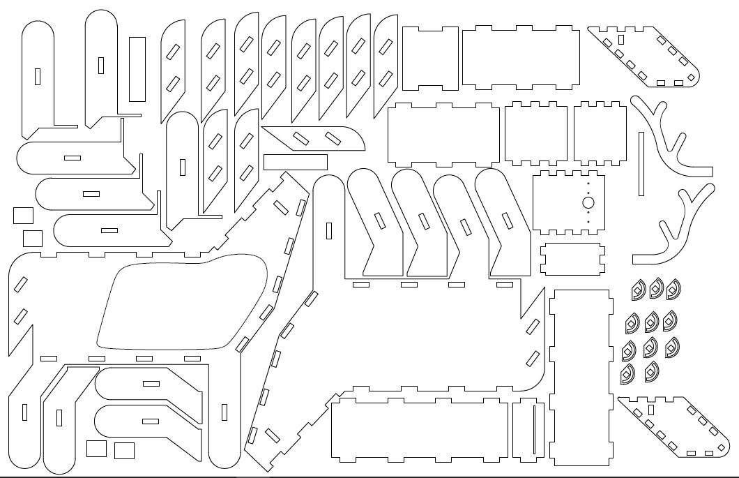
The standing part consist of 37 parts and it provides room for the Arduino, PCB and cables. The dimensions of the box are 110x70x40mm.
The moving part of the model is the head which rotates around the neck. The servo motor which provides the rotating motion was fixed on the top of the neck and the gear was attached to the bottom part of the head with glue and a screw. The consist of 20 parts.
During the project we designed and produced 4 different circuit board components. 3 of them were built for testing purposes, and the last one was built for the final product. By the end of it, we developed a quick and straightforward workflow to make these boards. The workflow can be summarized by the following steps:
The following table lists the exact number of electronic components used in the product:
| idx | part name | qty. | supplier | catalog no. | in list? |
|---|---|---|---|---|---|
| 1 | Arduino Uno | 1 | DigiKey | 1050-1024-ND | yes |
| 2 | Resistor 100 Ohm | 8 | DigiKey | 311-100FRCT-ND | yes |
| 3 | Orange LED | 8 | no | ||
| 4 | Blue LED | 8 | no | ||
| 5 | Micro servo motor | 1 | Jameco | 2214601 | yes |
| 6 | 2.54 header pins | 12 | no | ||
| 7 | Phototransistor | 1 | DigiKey | 1080-1380-1-ND | yes |
The light intensity sensor serves as a general on/off switch for the product electronics. Thus it does not have to provide precise measurements. This is achieved by a common emitter phototransistor circuit. The design of this circuit was performed in 3 steps: two standalone boards were created for testing purposes, and the final circuit is placed on the main board of the end product.
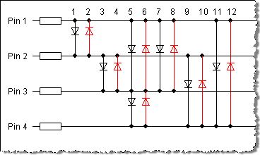
We lit the LEDs on the circuit board with the charlieplexing method. This is similar to multiplexing as it also aims for driving a number of LEDs using a small number of microcontroller pins. The following differences can be stated:
Advantages of charlieplexing:
O(n^2) of the used microcontroller GPIO pins. The exact number is n*(n-1)Disadvantages of charlieplexing:
10 mAAn additional problem raised with the layout designs: the charlieplexing method requires a lot of traces connecting the pins and the LEDs. It was difficult to arrange them on a single sided PCB. The automatic wiring algorithm of EAGLE was to good use. At first we planned to place 20 diodes on the board, but it didn’t seem to be feasible, so the number has been decreased to 16.
For the documentation we used the github webpage assigned to our project. We used jekyll to generate the website and chose a fitting template. To make it easier to get started with blog posting, Aleks created a short readme. The website reflects our thoughts and work processes and can be understood as a diary.
While the reindeer shape was being designed and in production Aleks created a simulation to come up with some ideas for the LED patterns. The attempt to create the simulation with PythonQt and Kivy were abandoned due to the time required and as a solution the Godot Engine came in handy. Godot is an open source game engine using its own scripting language GDScript which fortunatelly reminds of Python. This and the examples on the internet made the work quite easy. Also the IDE is suitable for all distributions and worked very well.
Originally the reindeer should consist of 10 red and 10 white LEDs, based on these the simulation has only these colors. Eight different patterns were created to run on the Arduino in the future and to get an idea what would look nice. The LEDs were later replaced by SMD ones because of the low brightness in a revision of the reindeer design.
The software running on the Arduino is quite straightforward, no external libraries were used. There are two non-trivial spots that are worth to be pointed out:
The first, naive implementation for the charlieplexing featured a 1 ms delay command after checking on every LED, even if the LED was turned off. For example: if the pattern ordered to switch between 2 diodes, each of them being lit 1-1 ms during the whole cycle, and nothing being turned on for n-2 milliseconds. In a later implementation this has been changed, and with the use of a timer, there are no empty time segments anymore.
Unfortunately, the final board has been manufactured so that the digital pin #6 controls the servo by PWM. As it turned out, this pin (along with pin #5) uses double the frequency as the others, which is too high for the servo. With some googling and hacking, the frequency could be changed, but it also affects the delay functions of the microcontroller.
| member | knowledge brought in | new stuff learned/improved | recommendations | future interests |
|---|---|---|---|---|
| aleks | diverse programming skills, soldering, microcontrollers, circuits (basics) | jekyll, board design (Eagle) and cutting, Godot, Arduino Uno | good commits on GitHub, show own initiative | board design |
| greta | Inkscape, github, sketching | documentation, jekyll, inkscape, operate fablab machines (lasercutter), design process (prototyping) | start soon, consider that not everything will work directly | Arduino programming |
| julia | 3D modeling | manufacturing | try to do the first prototypes asap | circuit design |
| lorinc | embedded hardware/software, circuit design, mechatronics | fabrication approaches, management | better inter-college management | practical opportunities in digital fabrication |