The LEDs on the reindeer shape are going to be driven by an Arduino Uno board. The course staff suggested to implement the charlieplexing method instead of driving the array with a shift-register. The charlieplexing method uses the high-impedance (input) state of the microcontroller pins reducing the number of the required components.
The following article was used as a reference for the design: Controlling 20 Led’s From 5 Arduino Pins Using Charlieplexing.
The number of LEDs to be driven by n pins is n x (n-1). On the final product we are going to use 5 pins, maximizing the number of LEDs at 20.
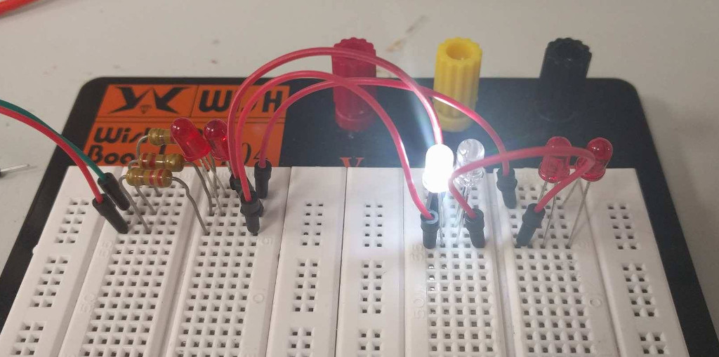
In order to test the method a circuit featuring 3 pins of the Arduino and 6 through-hole LEDs was assembled on a breadboard. The schematic of the circuit:
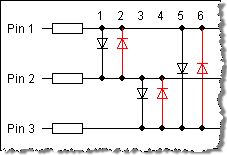
Which was driven by the following program on the Arduino:
#define NUM_LEDS 6

#define A 2
#define B 3
#define C 4

const int LED_MAP[NUM_LEDS][2] = {
  {A, B},
  {B, A},
  {B, C},
  {C, B},
  {A, C},
  {C, A}
};

void setup() {
  pinMode(A, INPUT);
  pinMode(B, INPUT);
  pinMode(C, INPUT);
}

void ledOn(int index) {
  pinMode(LED_MAP[index][0], OUTPUT);
  digitalWrite(LED_MAP[index][0], HIGH);
  pinMode(LED_MAP[index][1], OUTPUT);
  digitalWrite(LED_MAP[index][1], LOW);
}

void loop() {
  for(int i = 0; i < NUM_LEDS; ++i) {
    setup();
    ledOn(i);
    delay(200);
  }
}
Conclusion
The testing was successful, the LEDs lit up. However, the perceived lightness of the through-hole LEDs were quite low, which is going to be even worse if the number of diodes is increased. The next step is to check the SMD LEDs’ multiplexed intensity.